7.3 Powerstroke Glow Plug Relay Wiring Diagram Cadician's Blog
The glow plug control unit uses a glow plug relay to switch the current for the glow plugs on and off. The more glow plugs monitored by a control unit, the higher the current the circuit will need. To reduce the current needed, glow plugs are often distributed across two circuits, with two glow plug relays. This is often used in older glow plug.
Discovery Glow Plug Relay Wiring Diagram the wiring never sleeps
This is to me the best way to run your glow plugs for your GM 6.2 or 6.5 diesel engine. She fires right up every time and it allows you to control how long.
Bosch Glow Plug Relay Wiring Diagram Wiring Diagram
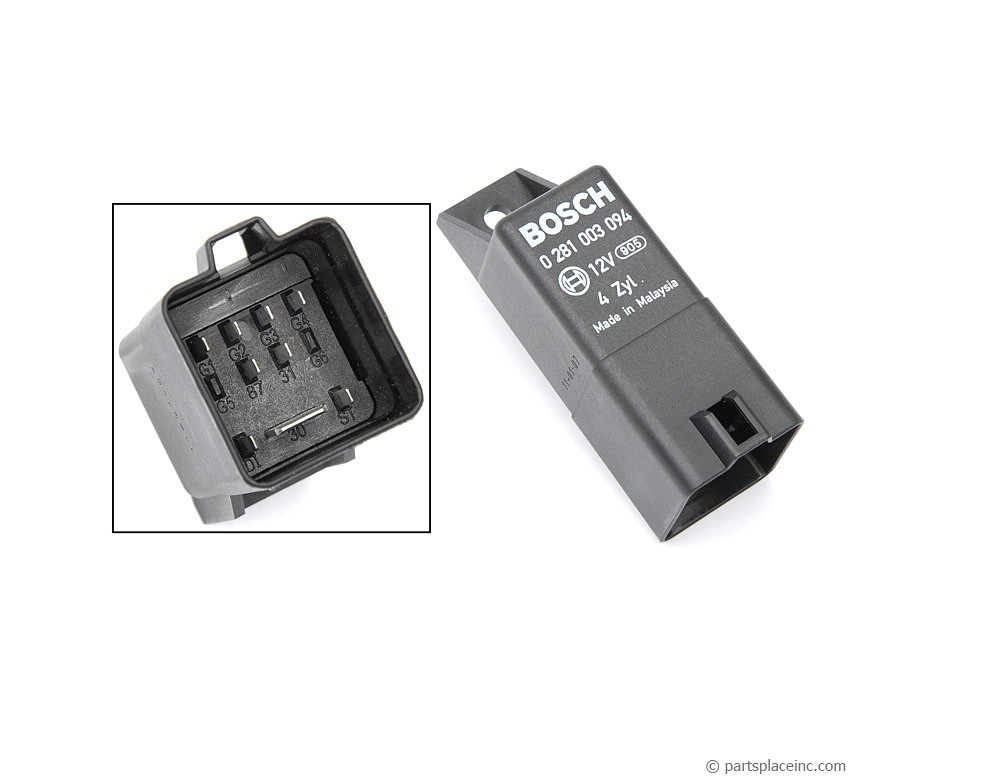
The white wire from the glow plug relay splices in to the white wire from the ignition switch and goes to the cold start warning light and to the fuel shut off solenoid. The black wire goes to the earth side of the cold start warning light. The black/yellow wire goes to the earth side of the fuel shut off solenoid; 1 = battery. 4 = 5 pin relay.
Glow plug relay issue Page 2 Diesel Bombers

In this video I show you how a properly working glow plug relay functions, as well as how to test and diagnose a bad one.
Glow Plug Relay Wiring Diagram Collection
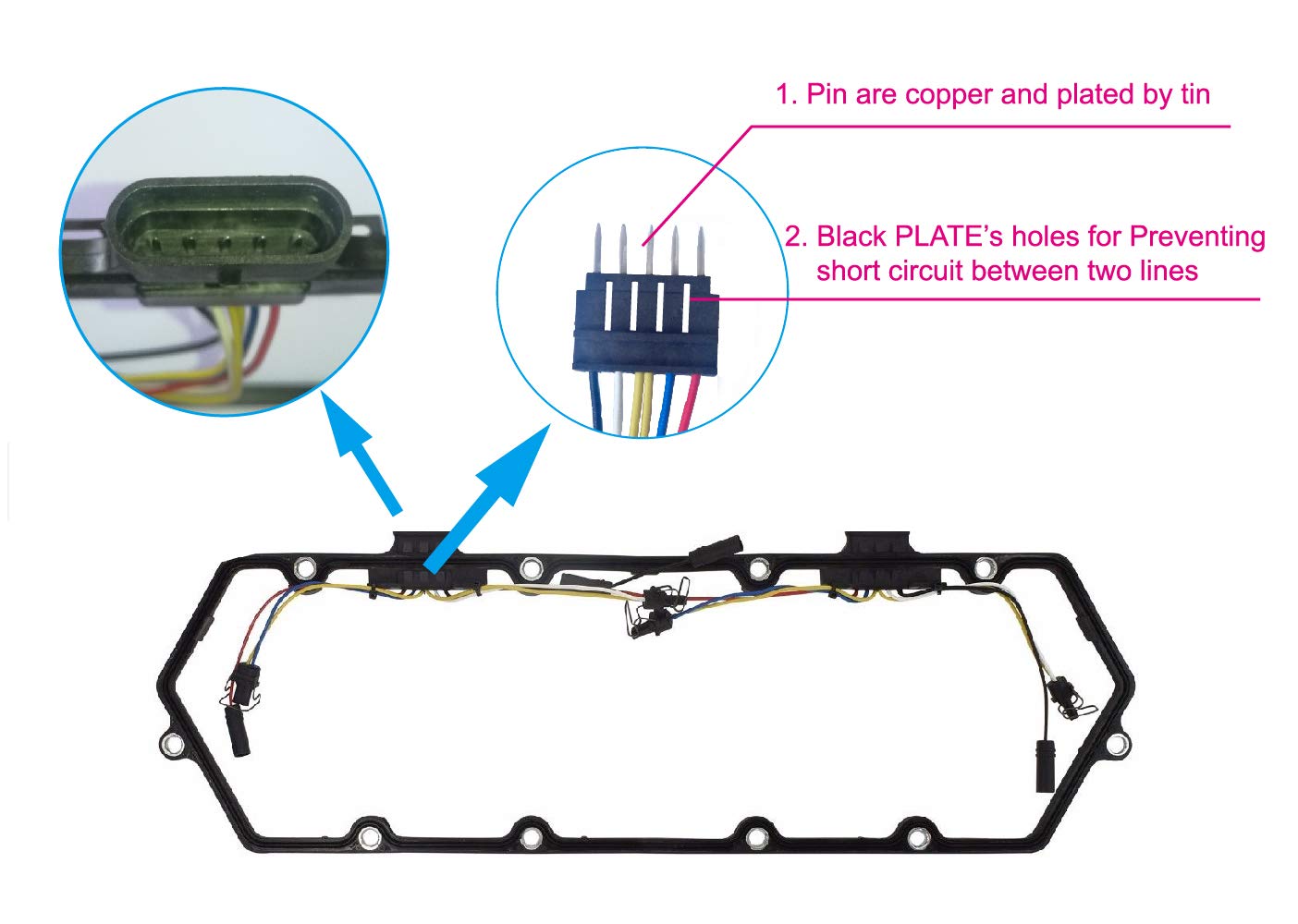
EASY CONNECTION OF GLOW PLUG WIRING DIAGRAM
Wiring Diagram For Glow Plug Relay 73

Motorcraft DY861 Glow Plug Relay : https://amzn.to/2HJboNR Digital Voltmeter : https://amzn.to/2EQM5rx Test light : https://amzn.to/3FYUbh6 Craftsman to.
2002 7.3 Powerstroke Glow Plug Relay Wiring Diagram Database
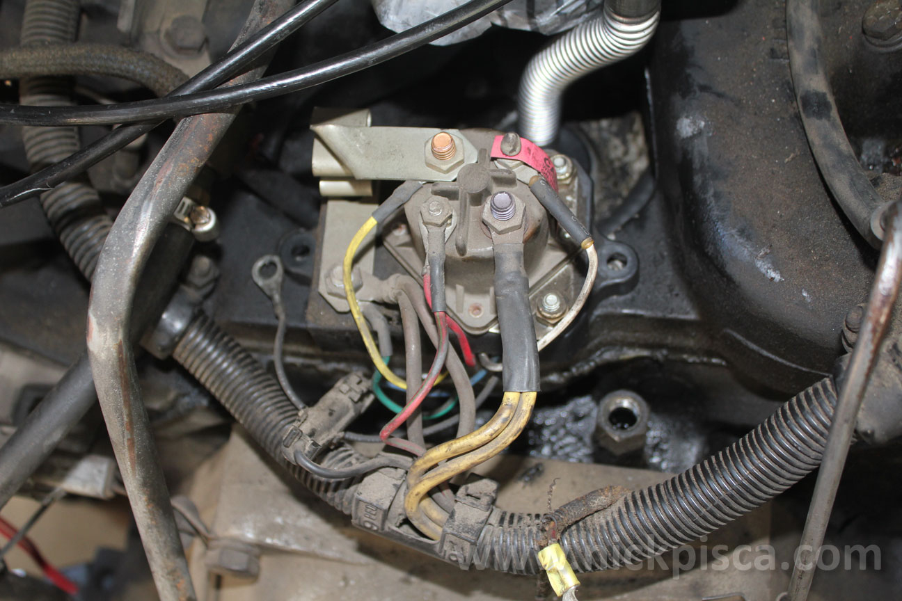
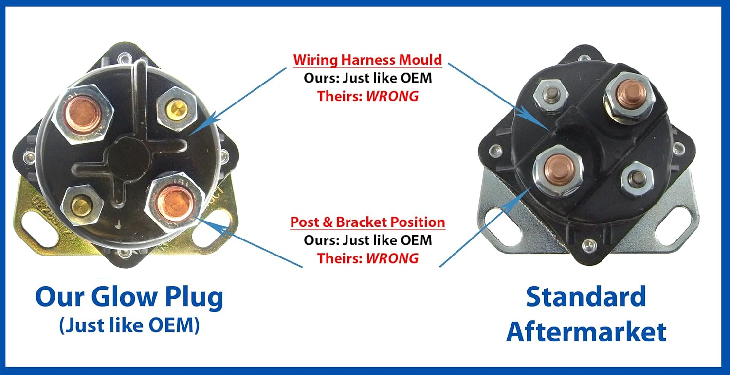
1999 - 2003 7.3L Power Stroke Diesel - Glow Plug Relay Wiring - I have a wire that is loose that I am reasonably certain goes to the GPR. Based upon the attached photo (courtesy of Guzzle7pt3.com), it is the wire that is labeled Purple Wire which is attached to the large terminal that feeds the both banks of GP's. The.
Discovery Glow Plug Relay Wiring Diagram the wiring never sleeps

The easiest is to check your glow plugs before testing your glow plug control module. To test your glow plugs, simply connect a 12-volt test light to the positive battery terminal. Then disconnect the wires from each of your glow plugs and touch the probe of the test light to the terminal of the glow plug itself (not the wiring harness).
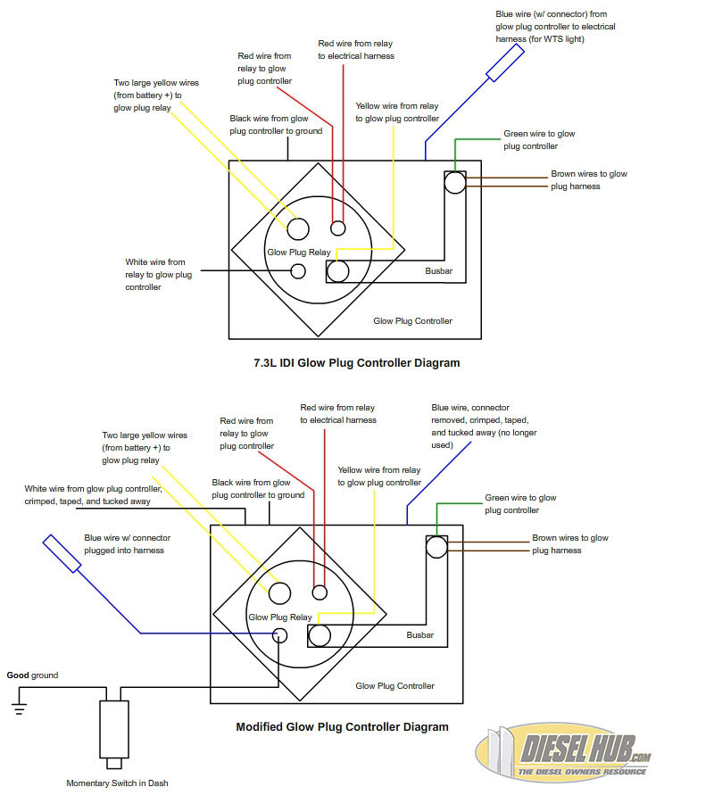
7.3 Idi Glow Plug Controller Wiring Diagram Wiring Diagram
That wire goes to pin 8 of the PCM (Glow Plug Monitor). Somewhere along the way there is a fusible link and wire changes color to White/Lt Grn. Attached Images. 1999 Drawing 1.pdf (75.4 KB, 5644 views) 1999 Drawing 2.pdf (67.2 KB, 3328 views) 1999 Drawing 3.pdf (63.4 KB, 3073 views) Reply Like.
7.3 Glow Plug Relay Test / Ford Super Duty 7 3l Powerstroke Glow Plug Replacement Procedure
The wiring diagram for the 7.3 IDI glow plug relay consists of several wires and connections that need to be properly understood and connected. One important wire in the glow plug relay wiring is the power source wire. This wire is usually connected to the positive terminal of the battery and provides the main power supply to the relay.
2001 7 3 Powerstroke Glow Plug Relay Wiring Diagram Wiring Diagram
Glow plug relay wiring. So today I bought a 1981 rabbit with the 1.6 diesel in it, the guy I bought it from had a rigged wire leading from the battery to the first glow plug, I got under the dash into the fuse box and located the relay, there are two wires that are disconnected from the socket (pictures shown) a solidblack/green stripe and a.
Glow plug relay?? Ford Truck Enthusiasts Forums
When it comes to the 7.3 glow plug relay wiring, it is essential to know how to replace the relay when it malfunctions.. Incorrect wiring can lead to poor performance or even damage to the relay. Refer to the wiring diagram for your specific vehicle to ensure the proper connections. Protective measures: Consider installing additional.
GLOW PLUG RELAY PROBLEMS Page 2 Ford Truck Enthusiasts Forums
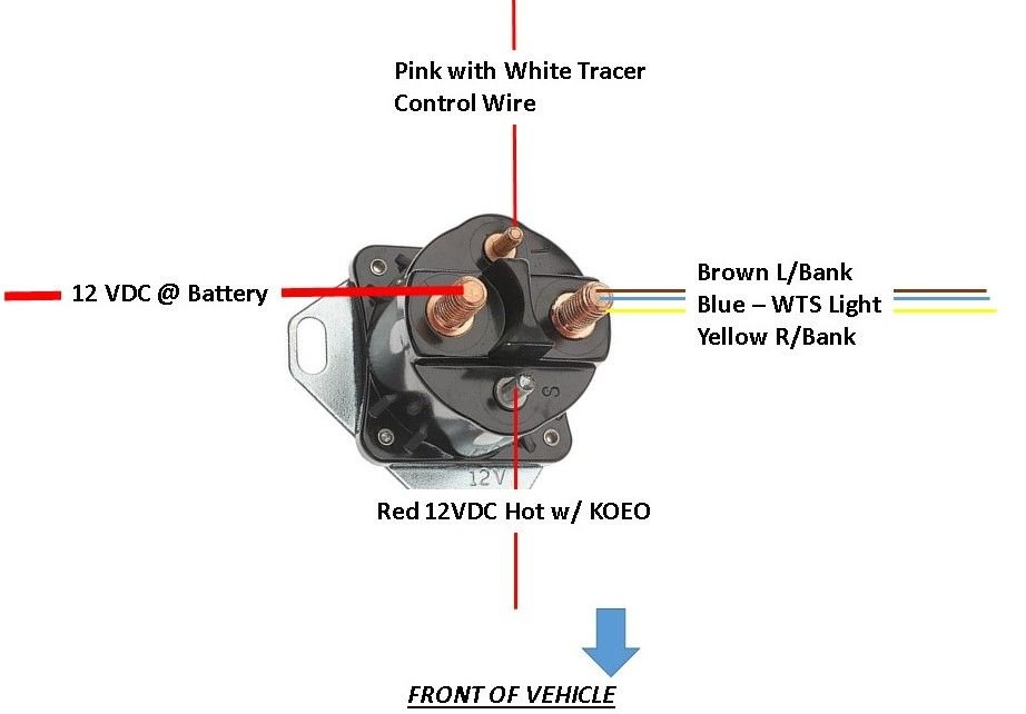
The 7.3 glow plug relay wiring diagram consists of several components, including the glow plug relay itself, the battery, the ignition switch, the fusible link, and the glow plugs. Each of these components plays a crucial role in the proper functioning of the glow plug system. Understanding the wiring connections between these components is.
7.3 Glow Plug Relay Wiring Diagram Collection
The glow plug timer relay is wired to the engine's main power source and connected to the glow plugs. It provides a controlled voltage to the glow plugs, allowing them to heat up and ignite the fuel-air mixture in the engine. The wiring diagram contains all the information needed to connect the relay to the engine's power source, as well as the.
1995 6.5 glow plug relay issues Diesel Bombers

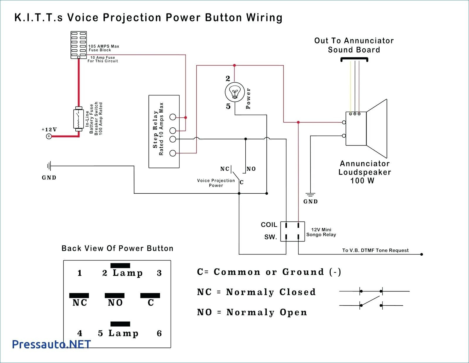
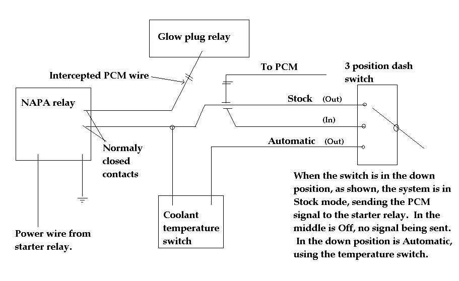
The switch is closed, sending current out pin 87 to the glow plugs (HM9) and the light micro-relay (HM99), by a voltage drop across pins 86 and 85 (left side of diagram). Turning the switch to "ignition" or "start" puts +12V at pin 86 (upper-right), so the glow plugs are triggered by sending ground to pin 85 (lower left).
7.3 Powerstroke Glow Plug Control Module Schematics Wiring Diagram Image
I think I found the diagram on WIS. Pin 8 on relay to glow plug 1 BKBU. Pin 7 on relay to glow plug 2 BKVT. Pin 6 on relay to glow plug 3 BKRD. Pin 5 on relay to glow plug 4 BKYE. I'm praying it's the relay dead, even though part more expensive, changing glow plugs is a days work. I can test resistance but with out direct access to glow plugs.